Impedance: The True Commander of Electronic Circuits
In middle school physics, we learned a golden rule: Voltage divided by Resistance equals Current $$\dfrac{V}{R} = I$$ This is Ohm’s Law, and in the world of Direct Current (DC), it is absolute truth.
But step into the world of Alternating Current (AC)—the signals running through your phone, your Wi-Fi router, or an ultrasonic sensor—and Ohm’s Law starts to break down. A resistor alone can no longer explain what happens to the current. This is where we need a more powerful concept: Impedance ($Z$).
What You’ll Learn
This article walks through four key ideas, each building on the last:
- Resistance — The familiar, frequency-independent part
- Reactance — The frequency-dependent part introduced by inductors and capacitors
- The Frequency Factor — Why impedance is meaningless without specifying frequency
- Phase — How impedance shifts the timing between voltage and current
By the end, you’ll understand why Impedance—not Resistance—is the true commander of any real-world circuit.

Resistance: The “Honest” Energy Consumer
Resistance ($R$) represents irreversible energy loss. When electrons flow through a resistor, they collide with atoms and convert electrical energy into heat. That energy is gone forever—much like friction in the mechanical world.
The key property of resistance is its simplicity: it behaves the same way regardless of signal frequency. Apply 5 V DC or 5 V at 1 MHz, and a 100 Ω resistor still dissipates power the same way.
$$ V = IR \quad \text{(Ohm’s Law)} $$
The “Cunning” Components: Inductors and Capacitors
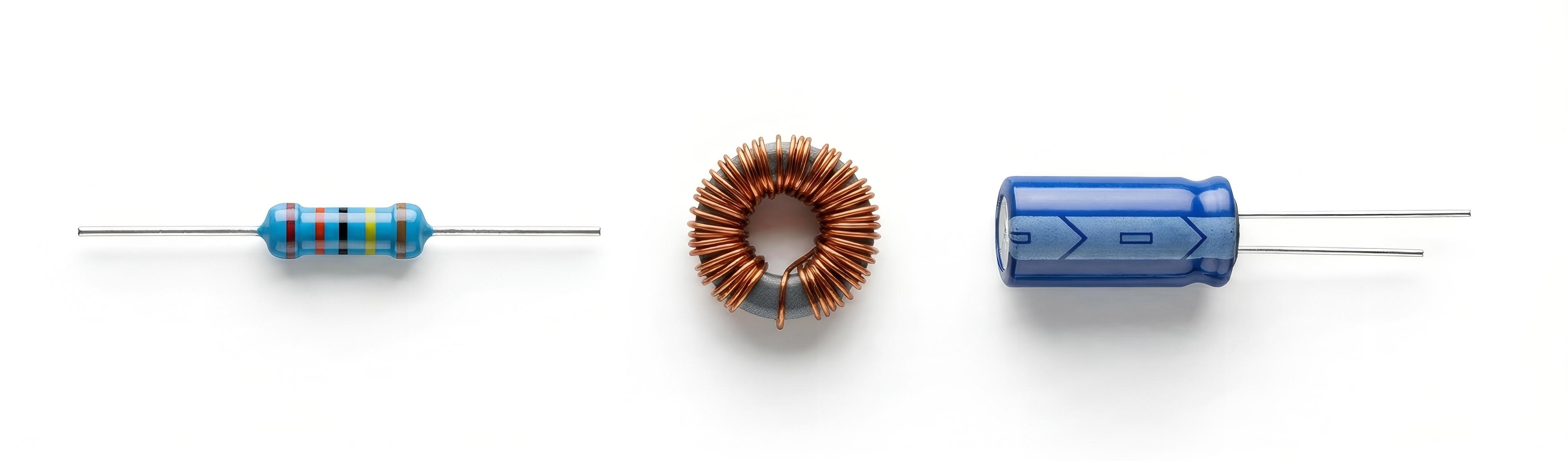
Real circuits contain more than resistors. Two special components—Inductors ($L$) and Capacitors ($C$)—do not consume energy directly, yet they still impede current flow.
| Component | What It Does | Energy Storage |
|---|---|---|
| Resistor | Converts energy to heat | None (dissipated) |
| Inductor | Opposes changes in current | Magnetic field |
| Capacitor | Opposes changes in voltage | Electric field |
When Resistance, Inductance, and Capacitance coexist in a circuit, we describe the total opposition to current as Impedance ($Z$)—a complex number with two parts:
$$ Z = R + jX $$
- Real part $R$: Resistance (energy consumed)
- Imaginary part $X$: Reactance (energy stored and returned)
The symbol $j$ is not just a mathematical convenience—it represents a 90° rotation in the complex plane, encoding the fact that stored energy is out of phase with dissipated energy.

The Frequency Factor: The “Sliding” Variable
Resistance stays constant across all frequencies. Reactance does not—it changes dramatically with frequency ($f$), which is why impedance only makes sense when you specify the operating frequency.
$$ \omega = 2\pi f $$
where $\omega$ is the angular frequency in radians per second.
Inductive Reactance ($X_L$)
For an inductor, higher frequency means larger opposition:
$$ X_L = \omega L = 2\pi f L $$
High-frequency current changes direction rapidly. The inductor’s self-induced EMF fights these rapid changes, creating greater opposition.
Analogy: Try pushing a heavy flywheel back and forth. The faster you reverse direction, the more the flywheel’s inertia resists you.
Capacitive Reactance ($X_C$)
For a capacitor, higher frequency means smaller opposition:
$$ X_C = \frac{1}{\omega C} = \frac{1}{2\pi f C} $$
At high frequency, charge flows in and out so quickly that the capacitor never fully charges—it barely impedes the current at all.
Analogy: Think of a revolving door. If people pass through quickly enough, the door never stops spinning—it offers almost no resistance to flow.

Resonance: The “Sweet Spot” Where $X_L = X_C$
Since inductive reactance rises with frequency while capacitive reactance falls, there must be a specific frequency where they perfectly balance each other out. This point is called Resonance.
When inductive and capacitive reactances are equal, they cancel out:
$$ X_L = X_C \implies \omega_0 = \frac{1}{\sqrt{LC}} $$
At this resonant frequency $f_0$, the impedance reduces to pure resistance ($Z = R$), and the circuit can absorb maximum energy. This is the principle behind tuning a radio to a specific station, designing filters, and matching antennas.

The Time Dimension: Phase
We arrive at the most physically profound feature of impedance: Phase.
With a pure resistor, voltage and current are perfectly synchronized—when voltage peaks, current peaks. They march in lockstep.
But inductors and capacitors break this synchronization. Because they take time to store and release energy, they create a time shift between voltage and current:
| Circuit Type | Phase Relationship | Mnemonic |
|---|---|---|
| Inductive | Current lags behind Voltage | ELI (E before I in L) |
| Capacitive | Current leads ahead of Voltage | ICE (I before E in C) |
ELI the ICE man — A classic mnemonic.
- ELI: In an inductor (L), EMF (Voltage) leads I (Current).
- ICE: In a capacitor (C), I (Current) leads EMF (Voltage).
The Phase Angle $\phi$ quantifies this shift:
$$ \phi = \arctan\left(\frac{X}{R}\right) $$
- $\phi = 0°$: Pure resistance (V and I in phase)
- $\phi = +90°$: Pure inductance (I lags V by a quarter cycle)
- $\phi = -90°$: Pure capacitance (I leads V by a quarter cycle)

Summary: The Commander of the Circuit
Resistance is just a special case of impedance—the case where frequency doesn’t matter and phase is zero.
In the real electronic world, Impedance ($Z$) is the complete picture:
| Property | Resistance ($R$) | Impedance ($Z$) |
|---|---|---|
| Domain | DC / pure resistive | AC / any circuit |
| Frequency | Independent | Dependent |
| Phase | 0° (V and I in sync) | $-90°$ to $+90°$ |
| Math type | Real number | Complex number ($R + jX$) |
| Energy | Dissipated only | Dissipated + Stored |
Understanding this distinction is the gateway to RF design, signal integrity analysis, impedance matching, and modern electronics.
References
- Horowitz, P. & Hill, W. (2015). The Art of Electronics (3rd ed.). Cambridge University Press.
- Pozar, D. M. (2011). Microwave Engineering (4th ed.). Wiley.
- Irwin, J. D. & Nelms, R. M. (2015). Basic Engineering Circuit Analysis (11th ed.). Wiley.