Transmission Loss vs Absorption Coefficient: What's the Difference?
Introduction: The Common Confusion
Have you ever tried blocking a noisy neighbor with acoustic foam (or worse, egg cartons), only to find you can still hear their TV perfectly?
This is the classic acoustics trap: confusing blocking sound with absorbing sound.
Both “absorption coefficient” and “transmission loss” describe how materials interact with sound. Both involve reducing sound energy. And both are critical in acoustic design.
But they answer completely different questions:
- Absorption coefficient (α): How much sound energy is converted to heat by the material?
- Transmission loss (TL): How much sound is blocked from reaching the next room?
The Energy Budget: Where Does Sound Go?
When a sound wave hits a surface, its energy splits into three parts:

- Reflected (R): Bounces back into the source room
- Absorbed (α): Converted to heat within the material
- Transmitted (T): Passes through to the other side
Energy conservation requires:
$$ R + \alpha + T = 1 $$
This simple equation is the key to understanding everything that follows. The absorption coefficient (α) and transmission loss (TL) each focus on different parts of this energy split—and that’s why they measure fundamentally different things.
Absorption Coefficient (α)
Definition
The absorption coefficient measures what fraction of incident sound energy is converted to heat within the material:
$$ \boxed{\alpha = 1 - R - T} $$
where:
- $\alpha = W_a / W_i$ is the absorption coefficient
- $R = W_r / W_i$ is the reflection coefficient
- $T = W_t / W_i$ is the transmission coefficient
This derived from the power balance $W_i = W_r + W_a + W_t$.
Physical Interpretation
The absorption coefficient quantifies irreversible energy dissipation within a material. In most practical absorbers, this dissipation arises from a combination of mechanisms:
- Viscous losses: Relative motion between air and solid surfaces within pores creates friction
- Thermal losses: Compression and expansion of the fluid phase causes heat exchange with pore walls
- Intrinsic material damping: Internal friction within the solid matrix
Materials with complex internal microstructures—such as porous foams and fibrous layers—typically exhibit high absorption coefficients because they maximize these loss mechanisms.
Characteristics
| Property | Value |
|---|---|
| Range | 0 (no absorption) to 1 (complete absorption) |
| Units | Dimensionless |
| Frequency-dependent | Yes (materials absorb differently at different frequencies) |
| Standards | ISO 354 (reverberation room), ASTM C423 |
What It Measures
- Room acoustics: Controlling reverberation and echo
- Speech intelligibility: Reducing flutter echoes
- Recording studios: Creating “dead” rooms for clean recordings
Typical Values
| Material | α (500 Hz) |
|---|---|
| Acoustic foam | 0.70 – 0.90 |
| Heavy curtains | 0.40 – 0.60 |
| Carpet on concrete | 0.30 – 0.50 |
| Painted concrete | 0.02 – 0.05 |
| Glass window | 0.03 – 0.10 |
Transmission Loss (TL)
Definition
Transmission loss measures how much sound power is blocked by a partition:
$$ \boxed{\mathrm{TL} = 10 \log_{10} \left( \frac{W_i}{W_t} \right) = -10 \log_{10}(T) \text{ dB}} $$
where:
- $W_i$ is the incident sound power (power hitting the partition)
- $W_t$ is the transmitted sound power (power radiating from the other side)
- $T$ is the transmission coefficient, defined as the ratio $T = W_t / W_i$
A higher TL means less sound gets through.
Physical Interpretation
Transmission loss quantifies the impedance to wave propagation across a structure. Unlike absorption, it is dominated by mechanisms such as:
- Inertia: Surface mass density resists acceleration by incident pressure waves
- Stiffness: Structural rigidity affects wave transmission, especially at low frequencies
- Resonance: At certain frequencies, structural modes can enhance or reduce transmission
- Wave interference: Phase cancellation between multiple transmission paths
In many cases, transmitted energy is minimized not by dissipation, but by reflection or phase cancellation. A rigid, heavy wall may therefore exhibit high transmission loss while absorbing very little acoustic energy internally.
The Mass Law
For a single, homogeneous panel under idealized conditions, transmission loss approximately follows the mass law:
$$ \mathrm{TL} \approx 20 \log_{10}(m \cdot f) - C $$
where:
- $m$ is the surface mass density (kg/m²)
- $f$ is frequency (Hz)
- $C$ is a constant dependent on the surrounding medium (≈ 47 dB for air at normal incidence)
Characteristics
| Property | Value |
|---|---|
| Range | 0 dB (open window) to 60+ dB (massive concrete wall) |
| Units | Decibels (dB) |
| Frequency-dependent | Yes (follows mass law at mid frequencies) |
| Standards | ISO 10140 (laboratory), ASTM E90 |
What It Measures
- Sound isolation: Blocking noise between rooms
- Facade performance: Keeping traffic noise out
- Privacy: Ensuring confidential conversations stay private
Typical Values
| Partition | TL (500 Hz) |
|---|---|
| Single glass (3mm) | 20 – 25 dB |
| Double glazing | 30 – 40 dB |
| Gypsum board (single layer) | 25 – 30 dB |
| Brick wall (100mm) | 40 – 45 dB |
| Concrete wall (200mm) | 50 – 55 dB |
The Critical Difference: A Comparison
| Aspect | Absorption (α) | Transmission Loss (TL) |
|---|---|---|
| Question answered | “How much energy is dissipated?” | “How much sound reaches the next room?” |
| Energy path | Incident vs. absorbed (heat) | Incident vs. transmitted |
| Units | Dimensionless (0–1) | Decibels (dB) |
| Key application | Room acoustics, reverb control | Soundproofing, noise isolation |
| Design goal | Reduce echoes | Block sound |
The Dangerous Misconception: Foam vs. Steel
This difference is best illustrated by comparing two common materials:

1. Acoustic Foam (High α, Low TL)
- α ≈ 0.85: Excellent absorber because it’s porous; sound enters and is converted to heat.
- TL ≈ 3 dB: Terrible blocker; sound passes right through the open pores.
2. Thin Steel Sheet (Low α, High TL)
- α ≈ 0.05: Poor absorber; almost entirely reflective.
- TL ≈ 25 dB: Decent blocker; density and inertia prevent sound transmission.
Beyond the Basics: Complexity in Real Systems
While the definitions above are clear-cut, real-world acoustic behavior can be counterintuitive.
The Helmholtz Resonator Paradox
A Helmholtz resonator (like a bottle with a narrow neck) perfectly illustrates the difference between these two metrics.
We often assume that to block sound, we must absorb it. But a Side-Branch Helmholtz Resonator works in the exact opposite way: it blocks sound effectively while absorbing very little.
Visualizing the Physics (Simulation)
To demonstrate this, we performed a Finite Element Method (FEM) simulation of a side-branch resonator mounted on a duct.
- Setup: A 1000mm waveguide with a small tuned resonator (Neck: 5mm length, 3.5mm radius).
- Result: At resonance (417 Hz), the resonator acts like a “sound mirror”.
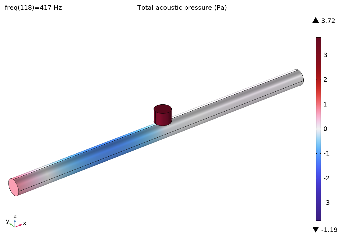
Why does this happen?
At resonance, the air in the neck oscillates vigorously, creating a zone of extreme high pressure. This creates a sharp impedance mismatch that effectively blocks the sound wave. Rather than being absorbed, the energy is reflected back towards the source.
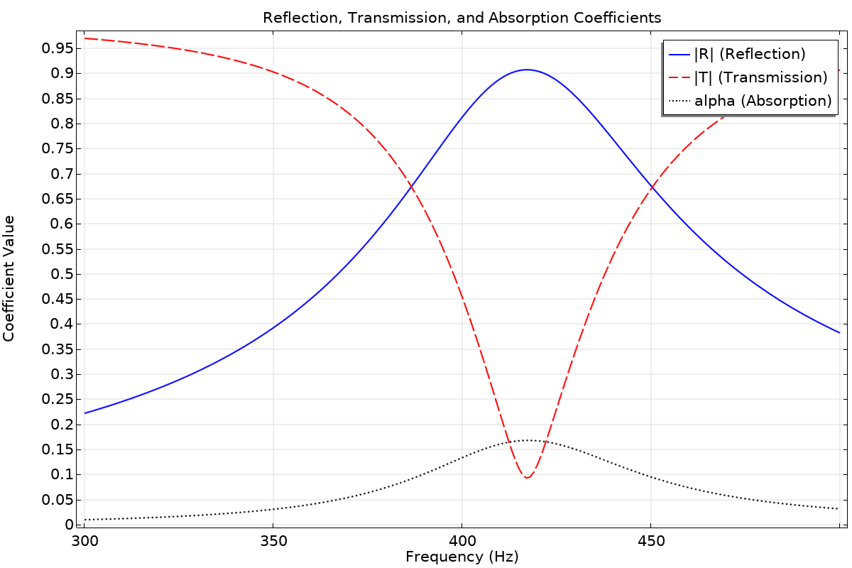

The Takeaway: You don’t need high absorption to have high transmission loss. You can block sound simply by rejecting it.
Frequency Dependence
It is critical to remember that both metrics are inherently frequency-dependent.
- Low Frequencies: Absorption becomes inefficient (wavelengths are too long for thin porous materials), and structural resonances dominate transmission.
- Mass Law Limits: The simple mass law breaks down near coincidence frequencies, where the panel is “transparent” to sound.
Coupled Systems
In advanced applications—such as double-wall assemblies or metamaterials—the two effects interact. Absorption in a cavity can suppress resonances that would otherwise ruin transmission loss, demonstrating how the two metrics, while distinct, can work together in a well-designed system.
Real-World Case Studies
How do we apply these principles in practice?
Case 1: Recording Studio
Goal: Create a quiet recording environment AND control reverb.
Solution:
- Walls: High TL (double-layer drywall, decoupled studs, mass-loaded vinyl)
- Interior surfaces: High α (acoustic panels, bass traps)
The most effective wall structures use a “Mass-Spring-Mass” system:
- Mass (outer layers): Drywall or brick provides high TL to block transmission
- Spring (air gap): Decoupled framing prevents vibration transfer
- Absorption (cavity fill): Fiberglass or mineral wool absorbs resonance trapped between the heavy layers
A studio needs BOTH metrics optimized—TL to block external noise, α to control internal reflections.
Case 2: Highway Noise Barrier
Goal: Block traffic noise from reaching residential areas.
Solution:
- Primary need: High TL (concrete, steel, or acrylic panels)
- Secondary consideration: Some α on the traffic side to reduce reflections back onto the road
Here, TL is critical. Absorption is a nice-to-have.
Case 3: Open-Plan Office
Goal: Reduce speech distraction so employees can concentrate.
Solution:
- Ceiling: High α (acoustic ceiling tiles) to reduce reverb
- Partitions: Moderate TL (if any) for visual privacy
Here, α is the main tool. TL between workstations is impractical.
Summary: Know What You’re Solving
| If your problem is… | You need… | Focus on… |
|---|---|---|
| Too much echo/reverb | Absorption | α (soft, porous materials) |
| Sound leaking to adjacent spaces | Transmission Loss | TL (mass, density, airtightness) |
| Both | Both | Composite solutions (mass + damping + absorption) |
The golden rule: Absorption controls sound within a space. Transmission loss controls sound between spaces.
References
- Bies, D. A., & Hansen, C. H. Engineering Noise Control: Theory and Practice. CRC Press.
- Long, M. Architectural Acoustics. Academic Press.
- ISO 354:2003 — Measurement of sound absorption in a reverberation room.
- ISO 10140-2:2021 — Measurement of sound insulation in buildings.