Behind the Powder: How SLS 3D Printing Is Transforming Manufacturing
When people think of 3D printing, they picture plastic filament squeezing out like toothpaste (FDM) or a model rising from a vat of liquid resin (SLA). But in the industrial world, engineers often prefer a technique that looks a bit “messy” yet delivers extraordinary results: Selective Laser Sintering (SLS).
Imagine excavating a structurally complex part—one strong enough to fly on an aircraft—from a pile of white powder, like an archaeologist unearthing an artifact. That is the magic of SLS. This guide pulls back the curtain on the technology, its strengths and limitations, and a new machine that is making industrial SLS accessible to smaller teams.
How It Works: Drawing with a Laser on a Powder Bed
SLS does not use ink or plastic filament. Its raw material is ultra-fine polymer powder—typically nylon.
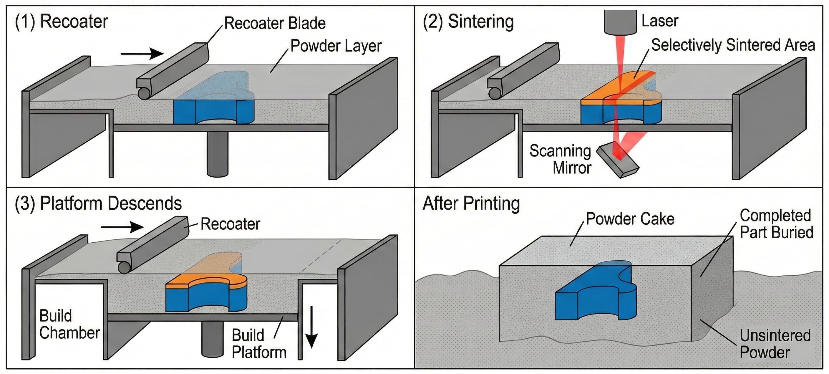
Think of it as building a sandcastle, layer by layer:
- Spread: A thin layer of powder (roughly 0.1 mm thick) is deposited across the build platform.
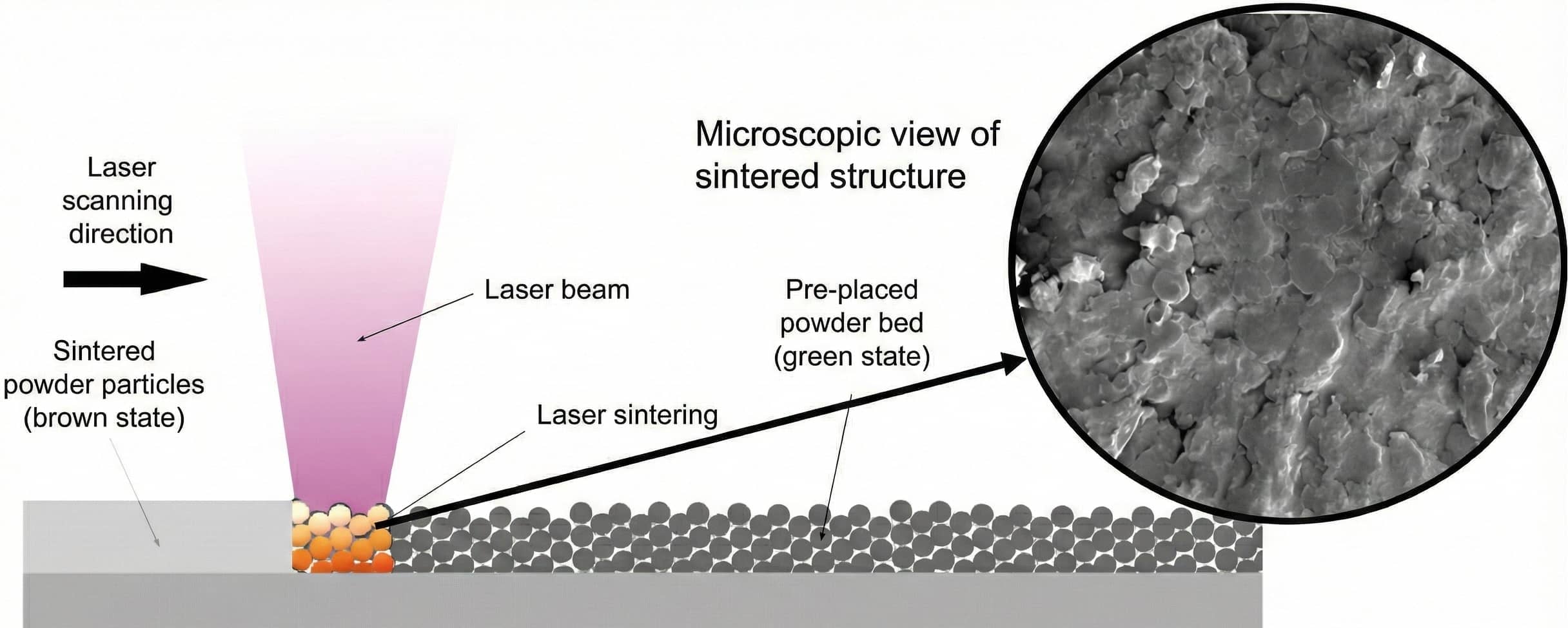
- Sinter: A high-power laser (CO₂ or fiber) traces the cross-section of the part according to the sliced CAD data. Where the beam strikes, powder particles heat up just below their melting point and fuse together—a process called sintering.
- Repeat: The platform lowers by one layer thickness, a fresh powder layer is spread, and the laser scans again. Each new layer bonds to the one beneath.
- Cool and Excavate: After thousands of layers, printing ends. What you see is a “cake” of powder. Once cooled, you dig the part out from the loose, unsintered powder.
The Superpowers of SLS: Why Engineers Love It
Compared to other additive technologies, SLS boasts several compelling advantages:
Zero Support Structures
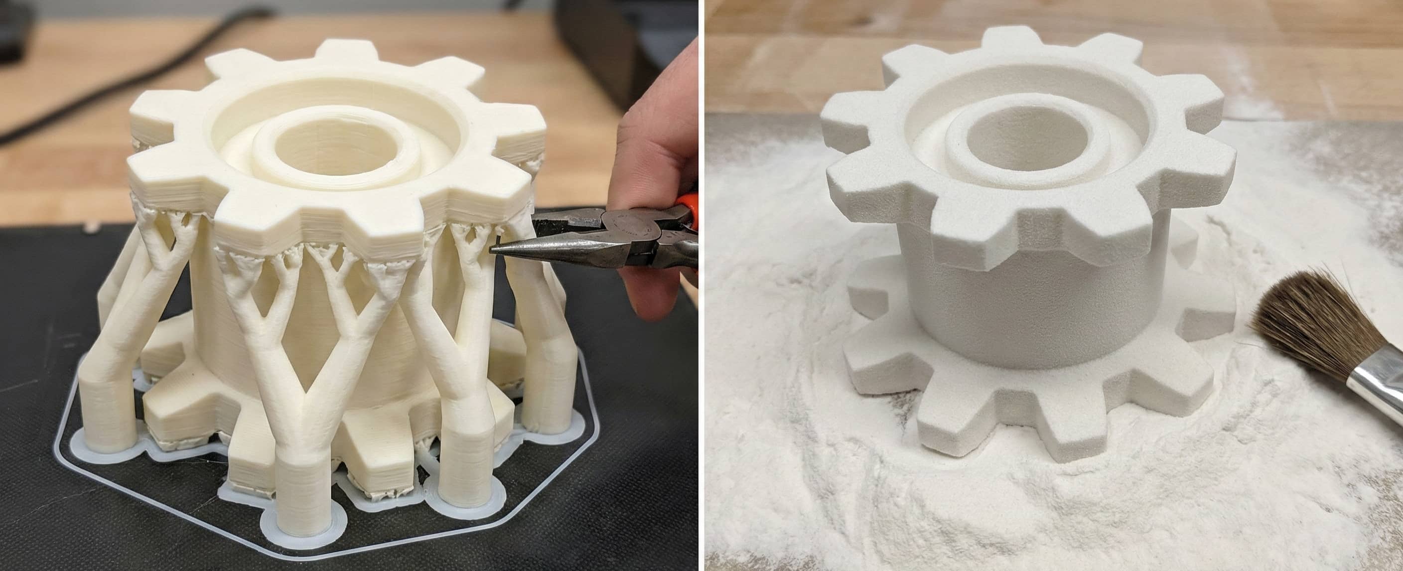
This is SLS’s greatest trick. In FDM or SLA, overhanging features require printed support scaffolding to prevent collapse. Those supports must later be removed, often leaving scars or adding labor.
In SLS, the unsintered powder itself acts as the support. You can print impossibly intricate geometries—internal channels, hollow lattices, even a chain-link mesh in one shot—without designing or removing any supports.
Isotropic Strength
FDM parts behave like wafer biscuits: the bond between layers is weaker than within a layer, so they tend to crack along layer lines under stress. SLS parts, by contrast, achieve near-isotropic mechanical properties—strength in the vertical (Z) direction closely matches the horizontal (X/Y) directions. This makes SLS suitable not just for prototypes, but for end-use parts under real mechanical loads.
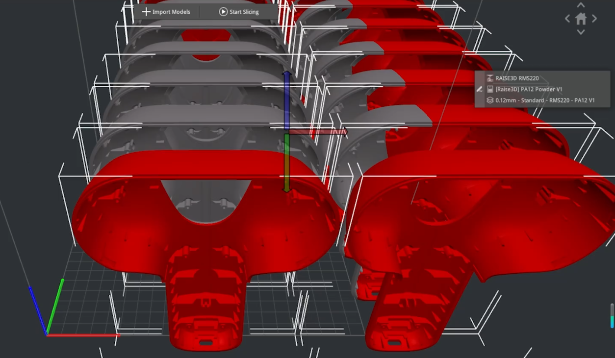
High Throughput via Nesting
Since no supports are needed, you can pack the build volume like a 3D Tetris game—stacking hundreds or thousands of parts throughout the powder bed. This “nesting” strategy maximizes machine utilization and slashes per-part cost for batch production.
Materials: What Are We Sintering?
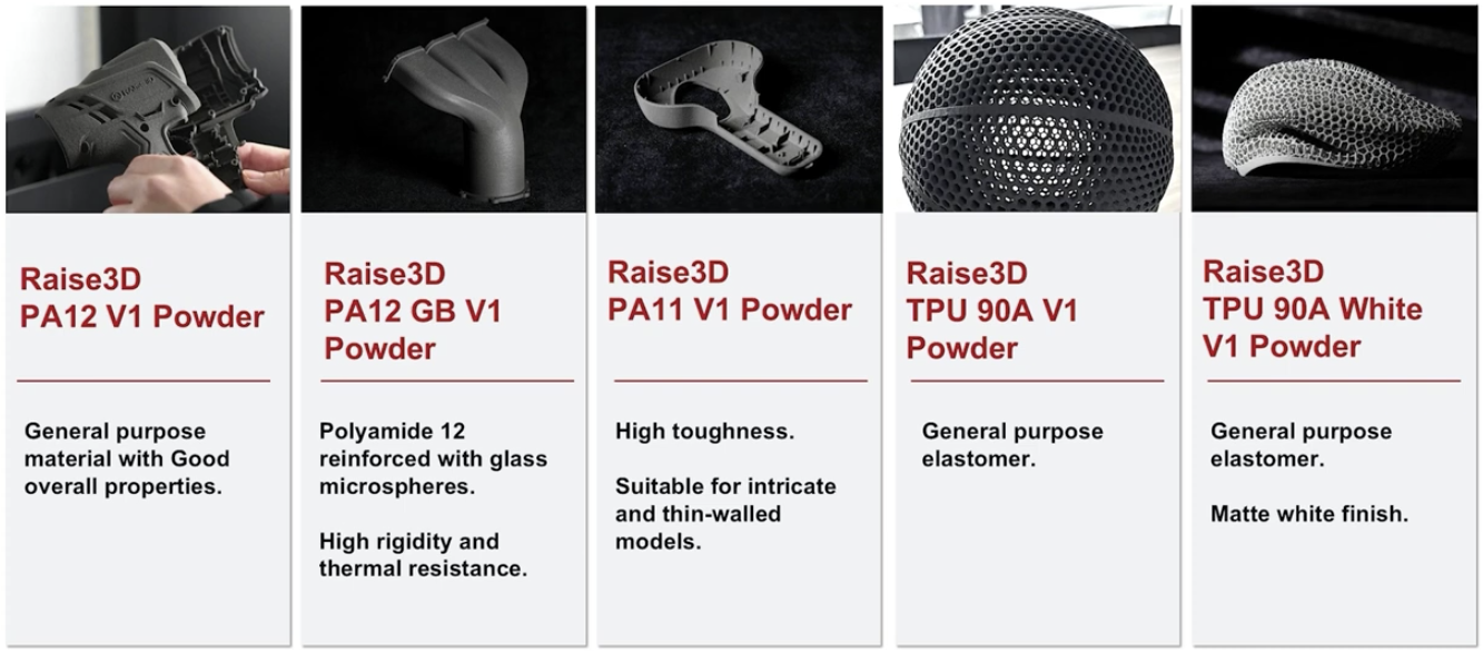
The most common SLS material is nylon (polyamide, PA)—a genuine engineering plastic.
- PA12 (Nylon 12): The industry workhorse. It is strong, durable, UV-resistant, and absorbs little moisture. From drone housings to snap-fit clips, the majority of SLS parts are PA12.
- PA11 (Nylon 11): More flexible and impact-resistant than PA12, making it ideal for living hinges or insoles that must flex repeatedly.
- TPU (Thermoplastic Polyurethane): A rubber-like elastomer. TPU is both soft and abrasion-resistant—perfect for seals, gaskets, or protective gear.
- Composites: Need extra stiffness? Add glass fiber (GF). Need lighter weight with higher strength? Add carbon fiber (CF).
Real-World Applications: Where SLS Shines
SLS is not about making trinkets—it is about making products.
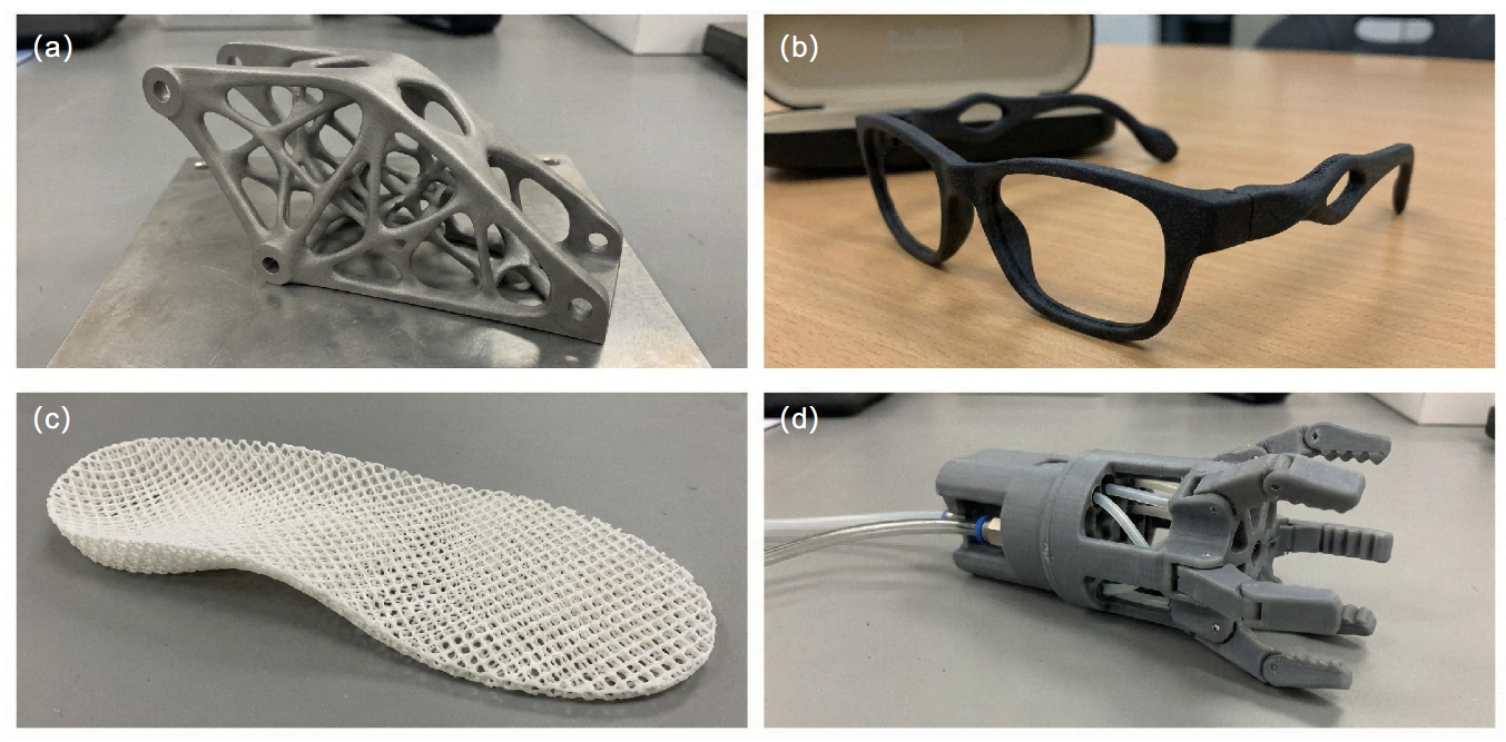
Aerospace: The Art of Weight Reduction
Every gram on an aircraft translates to fuel cost. Leveraging SLS’s support-free capability, engineers design intricate lattice or topology-optimized structures that retain strength while shedding mass.
Example: Environmental Control System (ECS) ducting—previously assembled from a dozen injection-molded pieces—can now be printed as a single, consolidated part. The result is lighter weight and fewer potential leak points.
Medical and Consumer Health: Personalization at Scale
Everyone’s body is unique; mass-produced medical devices rarely fit perfectly.
Example: Custom eyeglasses. A facial scan drives the design of frames that match the wearer’s nose bridge and temple width precisely. SLS prints them without molds—no minimum order quantity, zero inventory.
Example: Orthotic insoles and prosthetics. Using TPU, designers print lattice-structured insoles tailored to a patient’s gait and pressure map.
Industrial Automation: End-of-Arm Tooling
Robotic grippers often need to be custom-shaped for each product. SLS-printed grippers can embed internal air channels for vacuum actuation, eliminating messy external tubing. The result: lighter, cleaner, faster-cycling robots.
Limitations and Post-Processing: It Is Not Perfect Out of the Box
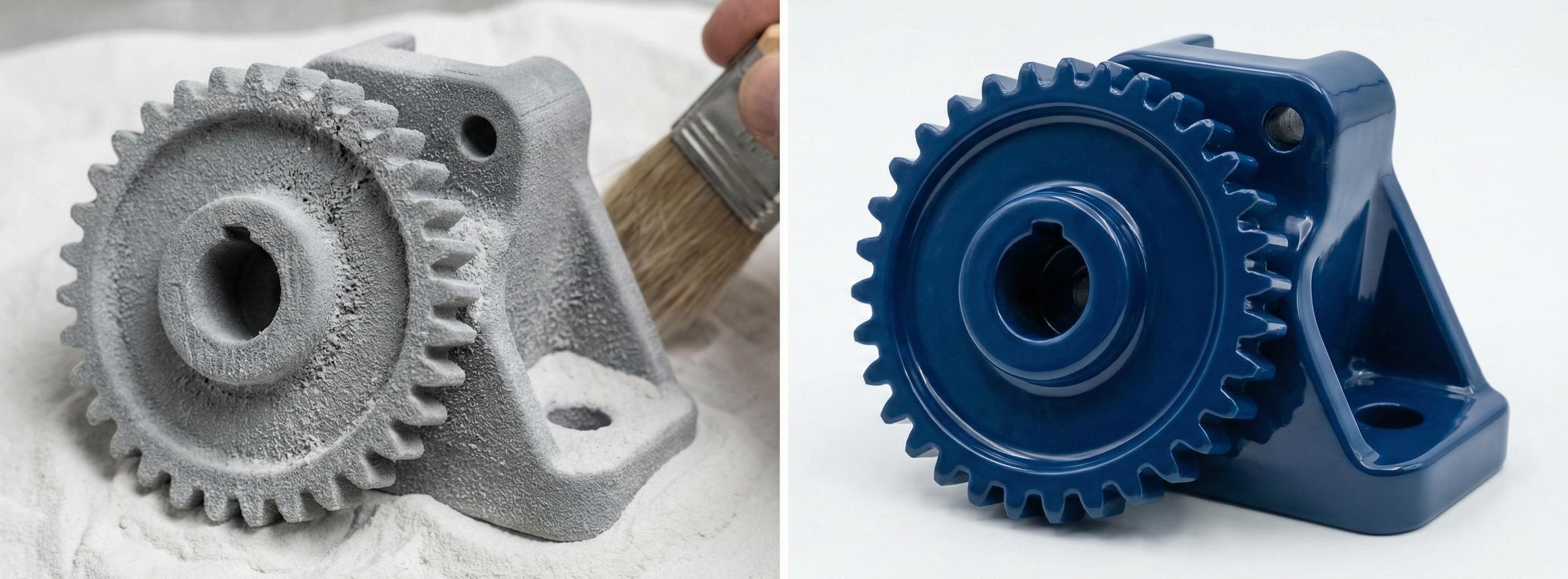
A balanced guide must be honest: raw SLS parts are not finished goods.
- Rough Surface: Parts emerge with a grainy, sandpaper-like texture—residual half-fused powder clinging to the surface.
- Required Post-Processing:
- Media Blasting: Mandatory. High-velocity air or glass beads knock off loose powder.
- Vapor Smoothing: The transformation step. Solvent vapor gently melts the surface, closing pores and creating a glossy, waterproof finish that rivals injection molding.
- Dyeing: Nylon is porous and readily absorbs dye. White parts can be colored in a wide range of hues.
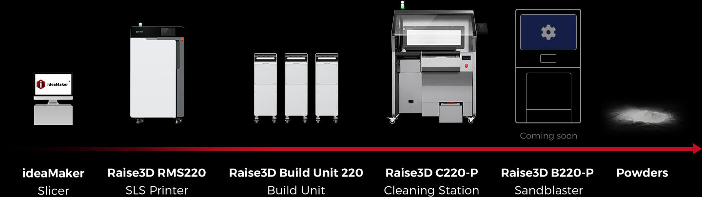
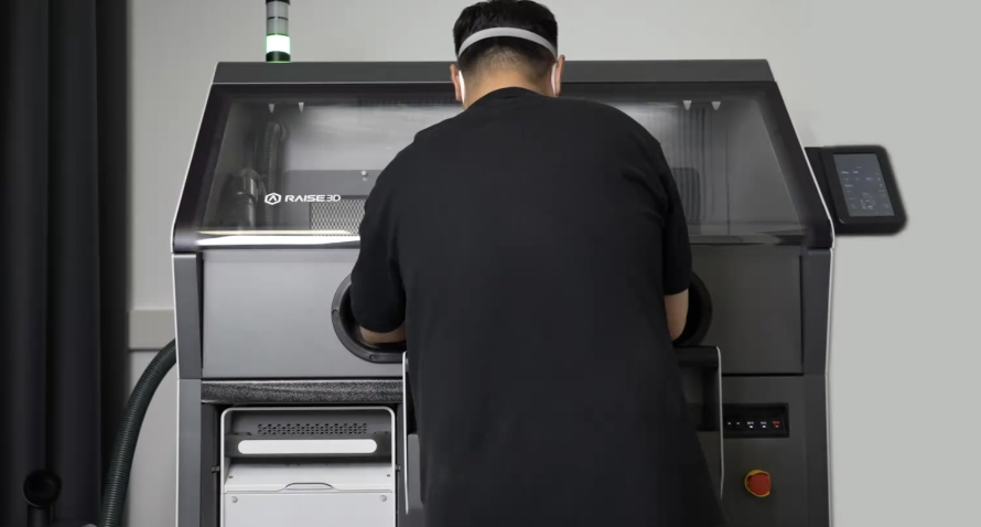
Spotlight: Raise3D RMS220—Industrial Power Meets Desktop Access
If SLS once belonged exclusively to large factories with million-dollar machines, a new wave of compact systems is democratizing the technology. Among the standouts in 2025 is the Raise3D RMS220.
Known for acclaimed FDM printers, Raise3D enters the SLS arena aiming to break the trade-off between price and performance.
Performance Beyond Its Footprint
Typical desktop SLS systems mount 10–30 W lasers. The RMS220 packs a 75 W fiber laser.
- Higher energy density enables processing not just standard nylons but also high-performance composites.
- Coupled with a 30,000 mm/s galvo scanner and a 200 µm spot size, the machine can produce up to 5 kg of parts per day—serious throughput in a compact footprint.
Modular Build Units: No More Waiting to Cool
A classic SLS pain point: after printing, you wait hours for the powder bed to cool before extracting parts.
The RMS220 solves this with swappable build units. Finish a print? Pull out the hot unit, insert a fresh one, and start the next job immediately. Think of it as swapping magazines in a firearm—uptime soars.
Closed-Loop Powder Handling
Powder dust is the reason many avoid SLS. Raise3D’s companion C220-P cleaning station automates depowdering, sieving, and mixing in a negative-pressure enclosure. Operators can work in office attire rather than hazmat suits.
Open Materials and Lower Consumable Costs
- Nitrogen Atmosphere: Printing under inert gas slows powder oxidation, allowing higher reuse ratios—PA12 refresh rates can drop to 20%.
- Open Material Program (OMP): Unlike closed ecosystems that lock users into expensive proprietary powders, the RMS220 supports validated third-party materials, trimming long-term operating costs.
Conclusion: Bridging Prototype and Production
SLS fills the vast gap between “handmade prototype” and “million-unit injection-molding run.” When you need dozens or hundreds of high-strength parts—or a geometry so complex that traditional molds cannot produce it—SLS is the answer.
It turns digital designs into robust physical objects, one thin powder layer at a time.
References
- Raise3D Official Product Page, RMS Series
- D.L. Bourell et al., A Brief History of Additive Manufacturing, Texas, 2009.
- EOS GmbH, SLS Materials Overview