Thermal Management of LED Light Fixtures in COMSOL Multiphysics
Introduction
In recent years, light-emitting diode (LED) bulbs have progressively replaced traditional incandescent and halogen bulbs for both indoor and outdoor lighting due to their superior longevity and energy efficiency.
However, thermal management remains a critical challenge. In LED bulbs, light is generated via electroluminescence as electric current flows through a semiconductor. In this process, approximately 70% of the consumed electrical power is converted into heat rather than light. If this heat is not effectively dissipated, the resulting high junction temperatures can drastically reduce the LED’s lifespan and efficiency.
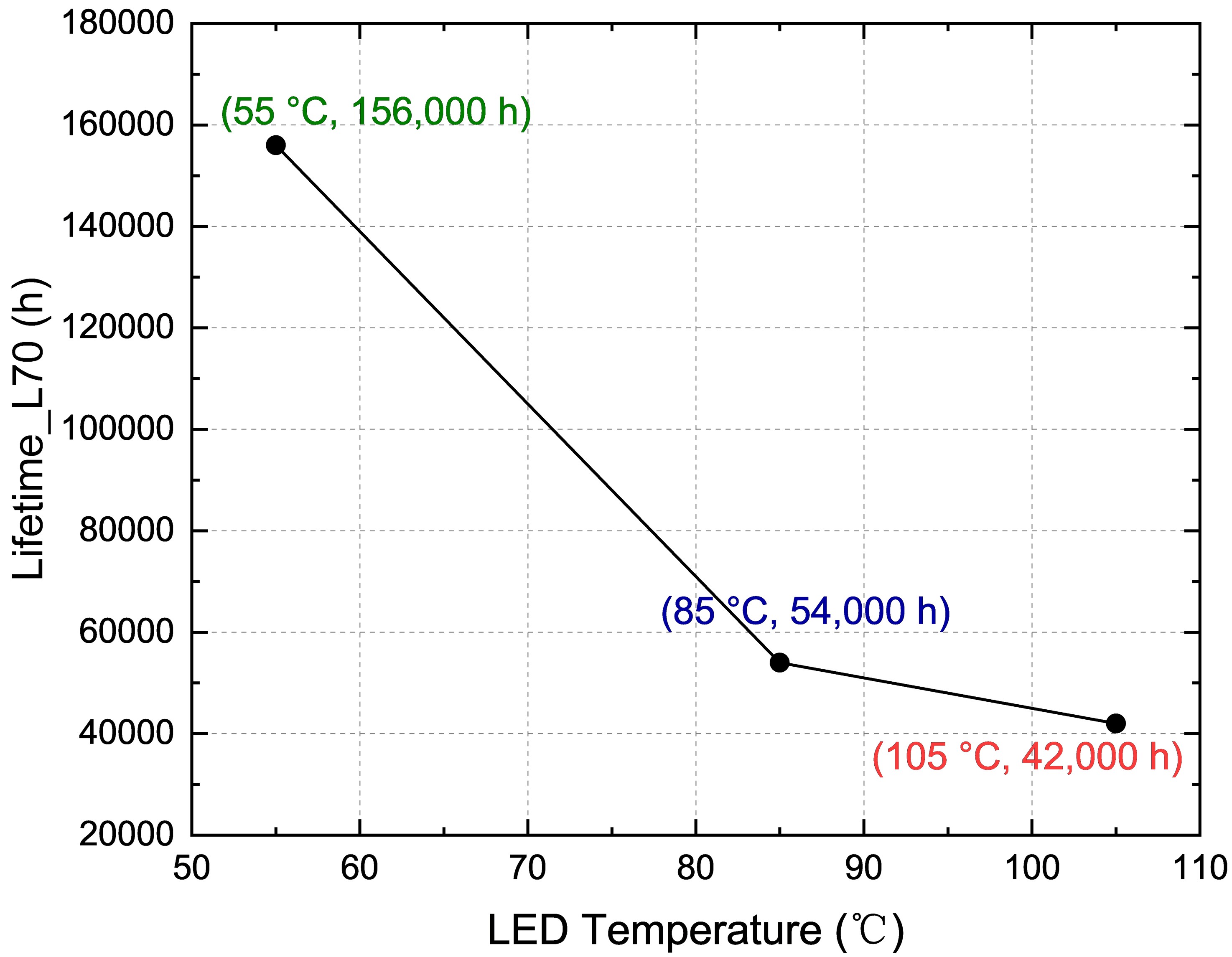
Empirical data highlights the severity of this issue. As shown in Figure 1, an increase in operating temperature from 55°C to 105°C can plummet the expected lifetime from 156,000 hours to just 42,000 hours. Therefore, optimizing the device geometry (e.g., chip arrangement, heat sink design, venting) and material properties (e.g., thermal conductivity, surface emissivity) is essential.
In this blog post, we demonstrate a COMSOL Multiphysics model to analyze the fixture’s thermal performance. For computational efficiency, this model focuses on conduction and radiation, while approximating convective cooling via boundary coefficients rather than solving for full fluid dynamics (CFD).
This example simulates the thermodynamic behavior of an LED fixture to evaluate the maximum operating temperature (junction temperature). It estimates the system’s equilibrium temperature by balancing the heat generation from the LED chips with cooling via conduction to the structure and radiation/convection to the ambient environment.
Model Definition
The fixture geometry consists of 1 lateral aluminum PCB, supporting 19 LED chips. The total nominal power of the bulb is modeled as 40 W. While radiation plays a role, surface-to-surface radiation between the internal aluminum PCB and the plastic bulb is neglected in this model because the view factors are primarily directed towards the surroundings. Numerical simulations have confirmed that including full internal surface-to-surface radiation significantly increases computational cost with negligible impact on the final temperature results.
Key parameters:
- Heat Source: The LED chips (epoxy resin) are welded onto the aluminum PCBs. Assuming a 70% heat dissipation rate, the total heat load is 7 W (based on 10 W input).
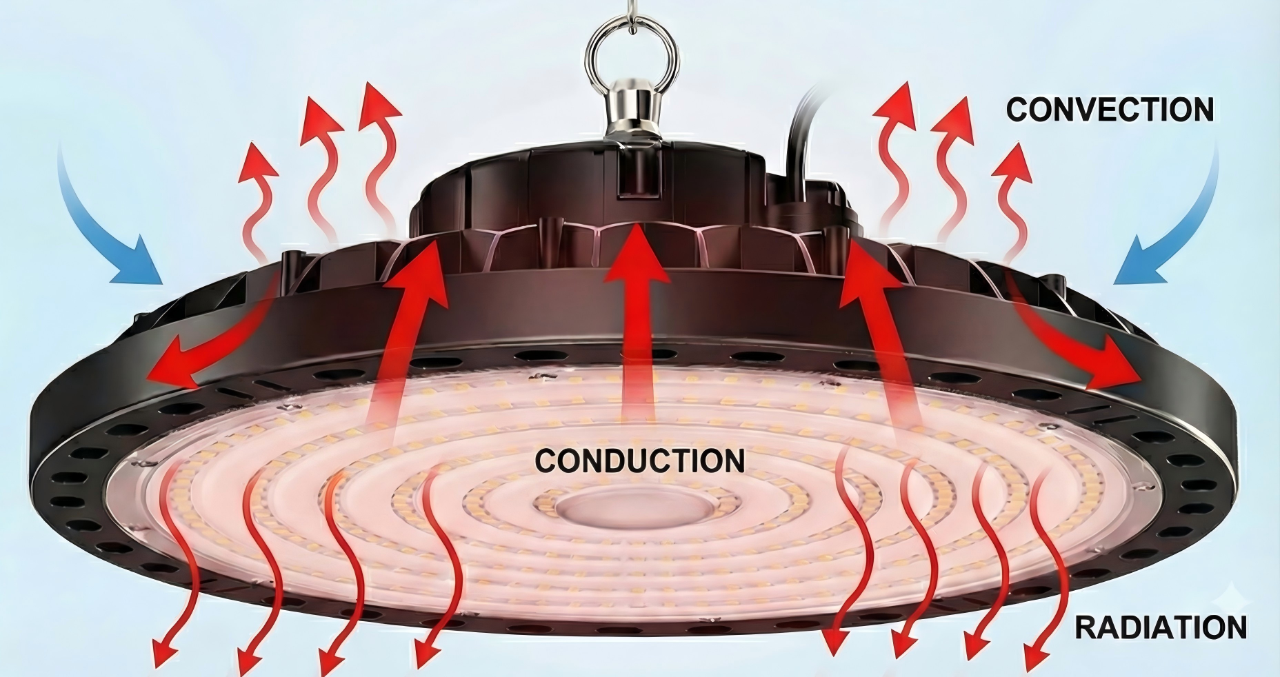
- Heat Transport: Generated heat is dissipated through conduction (into the PCB and base), radiation (surface-to-ambient), and natural convection (modeled via heat transfer coefficients).
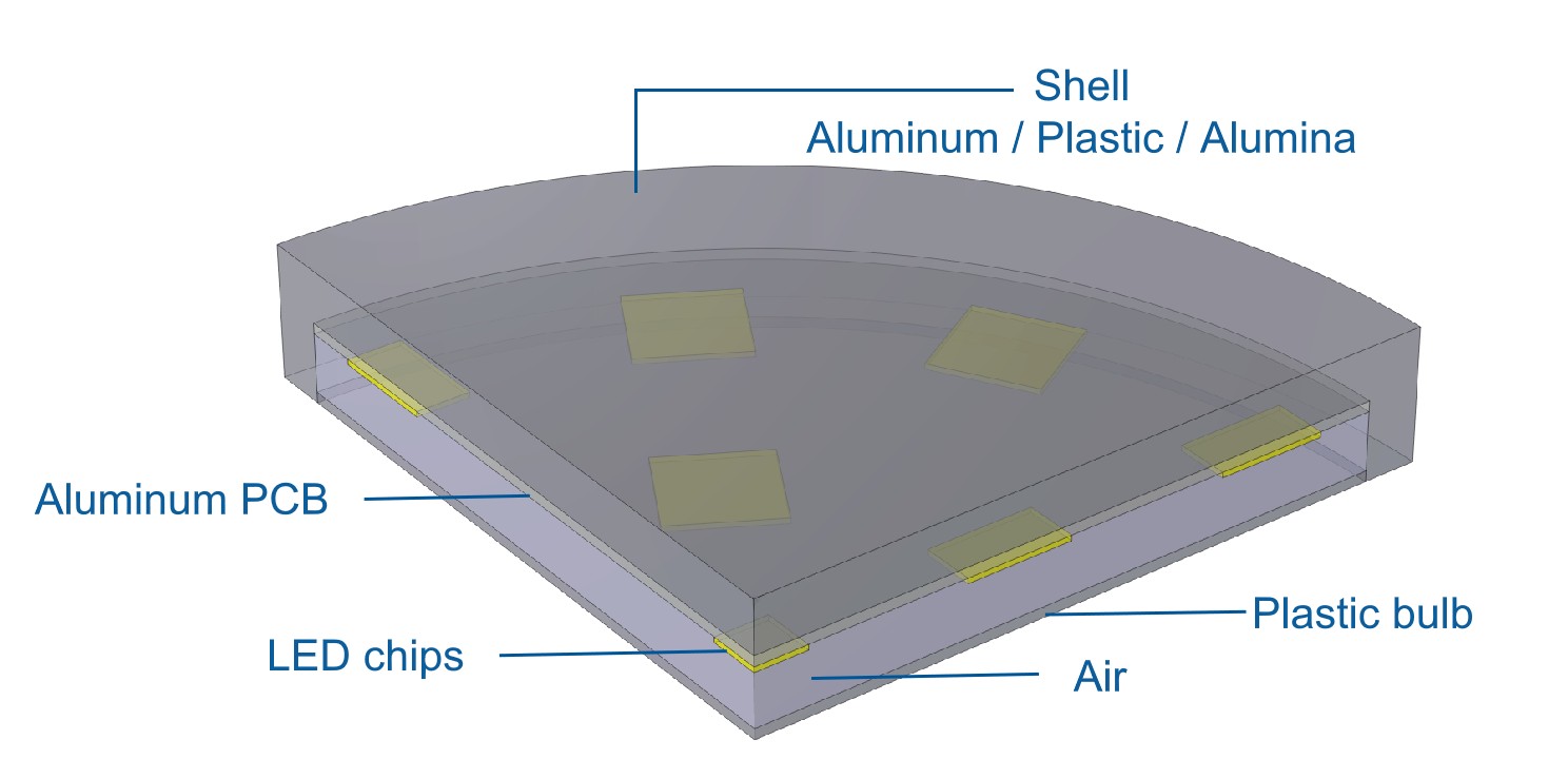
- Materials: The base of the LED bulb is modeled as steel; PCBs are aluminum; the bulb shell is plastic.
Symmetry
The LED geometry and operating conditions exhibit two clear planes of symmetry. Hence, it is possible to solve the equations on only one-quarter of the geometry, as shown in Figure 3.
Symmetry boundary conditions are applied to the heat transfer equations. Validation against full-geometry simulations confirms that this symmetry assumption does not compromise the accuracy of the cooling performance estimation.
Geometry
Figure 3 shows the LED bulb geometry used in the model. The LED chips are highlighted in orange, and the aluminum PCBs in brown.
- Domain: The device consists of PCBs inside a protective shell and a plastic bulb.
- Fluid Domains: Both the interior and exterior of the bulb are filled with air. The model assumes the bulb is sealed, meaning there is no mass flow exchange between the internal and external air domains, though heat is transferred across the shell wall.
Boundary Conditions
The physics setup includes the following boundary conditions:
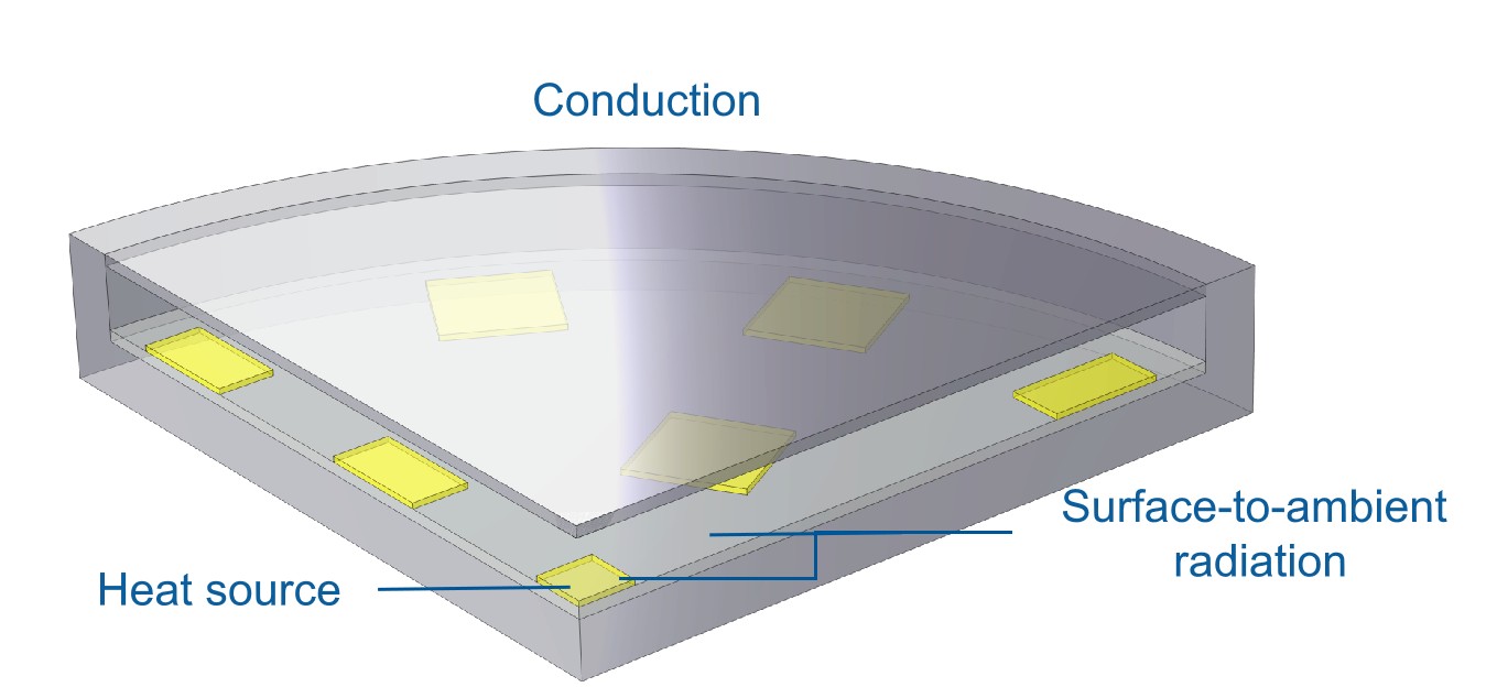
- Heat Source: LED chips are defined as volumetric heat sources.
- Surface-to-Ambient Radiation: Applied to the surfaces of the PCBs and LED chips to account for radiative cooling.
- Convective Heat Flux: Applied to external surfaces to represent natural convection cooling to the ambient air.
Results and Discussion
Preliminary Results
The initial simulation uses nominal design parameters:
Simulation Parameters (Nominal Case):
- Power: 10 W
- Spacing: 30 mm
- Environment T: 50 °C
- Shell Material: Plastic
- Computation Time: 10–20 s
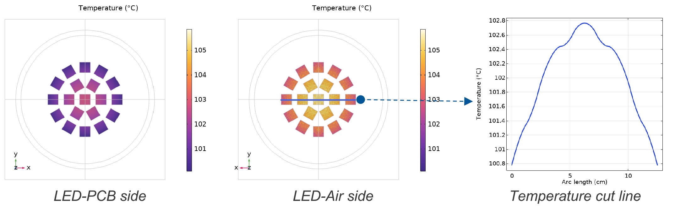
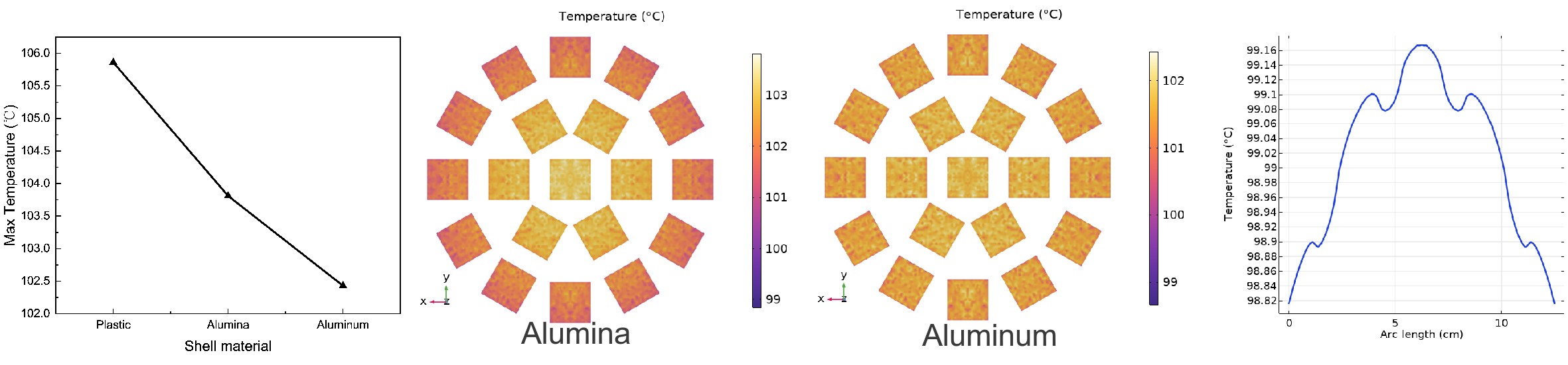
The temperature distribution reveals a clear gradient. Even within a single LED chip, the temperature is non-uniform. The side in contact with the PCB is cooler than the side facing the air, as the aluminum PCB acts as a heat spreader, conducting heat away more efficiently than the air can remove it via convection.
Looking at the cut-line of the LED array, the center of the array is hotter than the periphery. This is due to thermal cross-talk: chips in the center are surrounded by other heat sources and have a longer thermal path to the heat sink boundaries, whereas outer chips have better access to cooler regions. This temperature disparity can lead to uneven aging of the LED array.
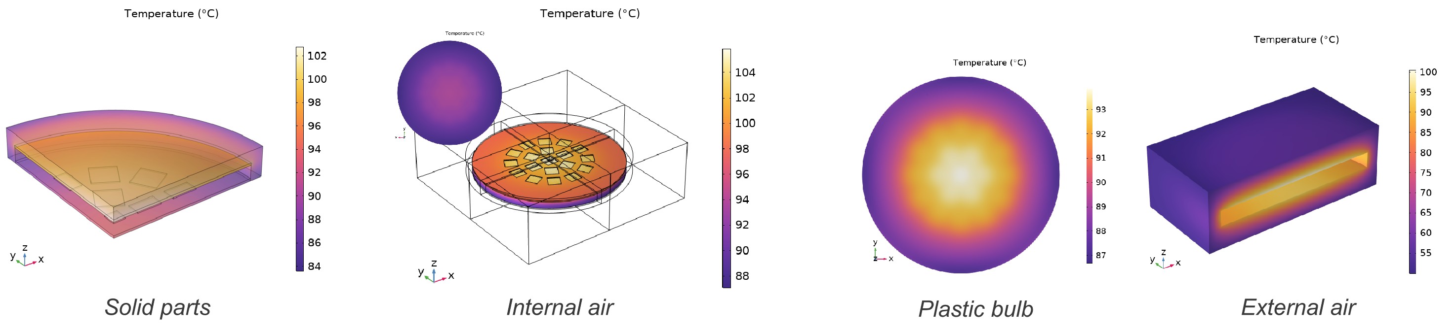
Cooling Mechanisms:
- LED Chips: Cooled primarily by conduction into the PCB and radiation to the air.
- Internal Air: Cooled by transferring heat to the plastic bulb wall, which then dissipates it to the ambient air.
Parametric Discussion
To optimize the design, we performed a parametric sweep of key variables.
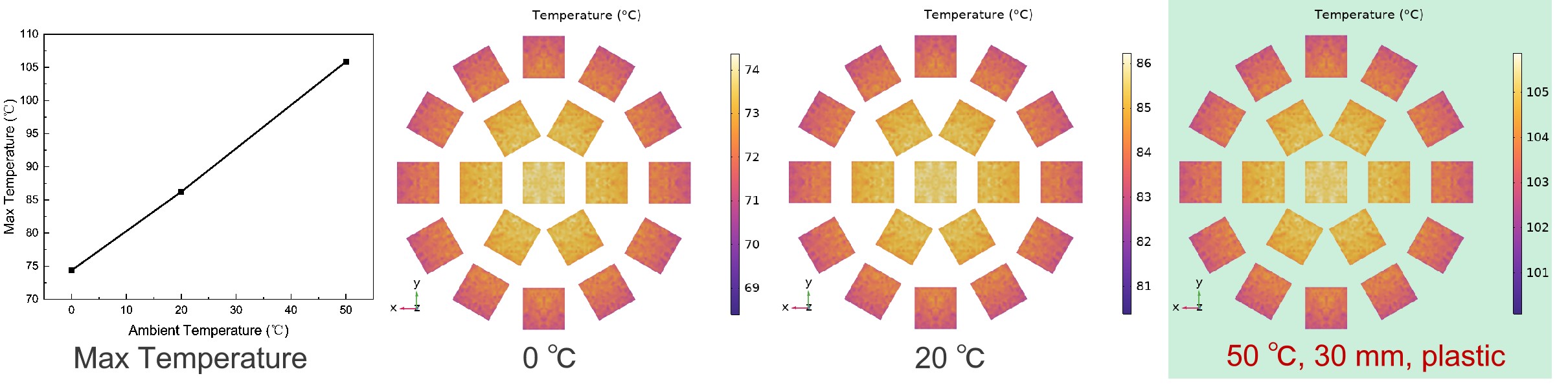
Ambient Temperature
Parameters:
- Power: 10 W
- Spacing: 30 mm
- Shell Material: Plastic
- Environment T: 0, 20, 50 [°C]
First, we varied the ambient temperature. As expected, the maximum temperature of the LED chips increases linearly with the environment temperature. The thermal patterns (hotspots) remain consistent.
Implication: The ambient environment is a baseline constraint. A fixture designed for indoor use (20°C) may fail or degrade rapidly if installed in an outdoor summer environment (40°C+).
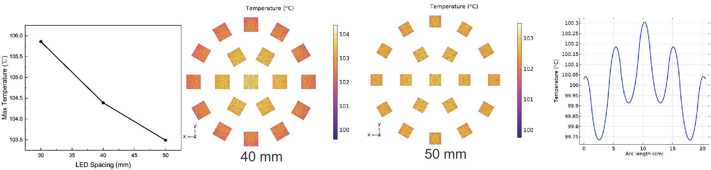
Geometry (LED Spacing)
Parameters:
- Spacing: 30, 40, 50 mm
Using the nominal model as a reference, we increased the spacing between LED chips.
Result: Both the maximum temperature ($T_{max}$) and the temperature difference ($\Delta T$) between chips decreased.
Analysis: Increasing spacing reduces the thermal resistance and thermal density. It allows the PCB to spread heat more effectively before saturation. Optimizing chip layout is a cost-effective way to improve thermal performance without changing materials.
Material Properties (Shell)
Parameters:
- Shell Material: Plastic, Alumina, Aluminum
We then modified the thermal conductivity of the outer shell material.
Result: Using a material with higher thermal conductivity yields results similar to increasing LED spacing—lower peak temperatures.
Analysis: A more conductive shell reduces the thermal resistance of the final heat rejection path (from internal air to external air), facilitating better overall heat dissipation.
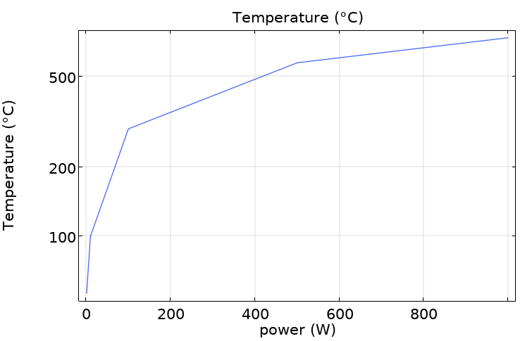
LED Power
Finally, we analyzed the effect of increasing the input power.
Result: The junction temperature rises sharply at lower power levels, but the rate of increase diminishes as power increases, exhibiting a non-linear behavior.
Analysis: While higher power input increases the heat generation rate, the temperature response is not proportional across the entire range. The initial steep rise suggests rapid heating, while the flattening curve at higher power levels indicates that heat dissipation mechanisms (likely radiation, which scales with $T^4$) become more dominant and effective at higher temperatures. This curve helps define the maximum rated power for the fixture to keep the junction temperature below the safety threshold (e.g., 85 °C or 105 °C).
Conclusions
This simulation highlights that thermal management is a multivariate problem.
- Ambient Temperature: Directly shifts the operating baseline.
- Geometry: Increasing chip spacing reduces hotspots and improves uniformity.
- Materials: High-conductivity shells enhance the final heat rejection step.
- Power: Must be capped based on the cooling capacity of the design.
Next Steps for Optimization:
- Refine Geometry: Adjust PCB thickness and fin structures based on manufacturing constraints.
- Validation: Correlate simulation results with physical thermocouple measurements to calibrate the heat transfer coefficients.
- Advanced Physics: Incorporate a full CFD analysis for the external air domain to better model complex installation environments and airflow patterns.